SEGMENT 8: SUPPLEMENTAL VIEWS
SECTION VIEWS
FULL SECTION
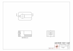 SHIFTER BLOCK
-A sectional view that shows an
object as if it were cut completely apart from one
end or side to the other. BREAK OUT SECTION, REVOLVED SECTION
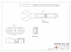 SADDLE BLOCK
-A section that shows an
object as it would look if a portion of it were cut
partly away from the rest by a cutting plane and
then “broken off ” to reveal the cut surface and
insides.
-A section, usually of a
long, thin object, that is rotated in place on the
drawing to show a cross section. 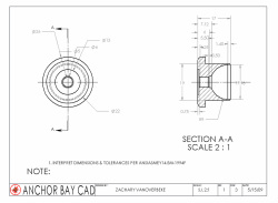 SPRING RETAINER |
OFFSET SECTION
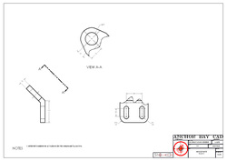
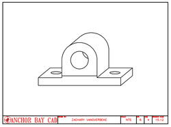
 HOLDER BASE
-A section in which the cutting-
plane line shifts to include features that would
not ordinarily be included in a section made by a
straight cutting plane. HALF SECTION
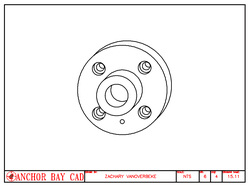
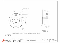 FLANGE
-One half of a full sectional view. |
- the path of the knife is a cutting plane.
- On the sectional view, the cut surface is marked with thin, evenly spaced lines, known as section lining.
- On the sectional view, the cut surface is marked with thin, evenly spaced lines, known as crosshatching.
- A full section is a sectional view that shows an object as if it were cut completely across from one end or side to the other.
- offset, or shifted, to show a detail or avoid a part known as an offset section.
- A half section is one-half of a full section.
- A view with a broken-out section shows an object as it would look if a portion of it were cut partly away by a cutting plane and then “broken off” to reveal the cut surface and insides.
- revolved section is a section, usually of a long, thin object, that is rotated in place on the drawing to show a cross section.
- When a sectional view is taken from its normal place on the view and moved somewhere else on the drawing sheet, the result is a removed section.
- When a cutting plane passes through the object at an angle , the resulting sectional view is called an auxiliary section, and it is drawn like any other auxiliary view.
- A phantom section, also called a hidden section, shows in one view both the inside and the outside of an object that is not symmetrical.
- An associative hatch updates the hatch as the hatched object changes.
|
SECTION 1
-Sectional views are used to show complex interior details. -Special section-lining patterns, or symbols, are used to represent specific materials. -Each of the various types of sectional views has a specific purpose; these views should not be used interchangeably. -Cutting-plane lines or centerlines may be used to show where a section is taken. -Hidden lines are used on sectional views only if they are needed for clarity. -Bolts, shafts, pins, and other similar parts are usually not sectioned even if the cut- ting plane passes through them. |
SECTION 2
-Sectioning techniques are available for board drafting and CAD to help save time in creating sectional views. -Accurate sectional views can be drawn with board techniques by using section line spacing and outline sectioning. -To develop a sectional-view drawing, first determine which normal views are neces- sary. Then decide what type of sectional view is needed to show interior detail with few, if any, hidden lines. -In CAD, section lining is often referred to as hatching. -When developing sectional views, planning is important to maximize efficiency. |
OTHER KEY TERMS
|
Content Vocabulary
cutting plane section lining crosshatching full section offset section half section broken-out section revolved section removed section auxiliary section phantom section hatching associative hatch |
Academic Vocabulary
method section primary |
Auxiliary Views
Primary Auxiliary
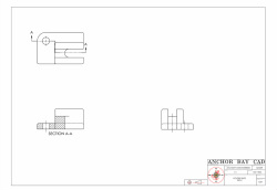
 ANGLE PLATE
-An auxiliary view
that is developed directly from one of the normal
views. |
Secondary Auxiliary
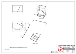 ANGLE SLIDE
-An auxiliary view
that is developed from a primary auxiliary view. |
|
SECTION 9.1
-An auxiliary view is required to solve problems involving inclined surfaces. -A partial auxiliary view is acceptable when some curves can be left out but the object is still described completely. A primary auxiliary view is one that is developed directly from the normal views. -Secondary auxiliary views are projected from primary auxiliary views. -Drawing an auxiliary section is another way to explain an object’s details. -Auxiliary views are developed by revolving the plane of projection. -The creation of an auxiliary view in CAD is similar to that used in board drafting but can be done in less time because the CAD software automates many of the more time-consuming tasks. |
SECTION 9.2
-A view projected from a primary view is a secondary auxiliary view. It is used to find the true size and shape of a surface that lies along an oblique plane. -An oblique plane is one that is inclined to all three of the normal planes. -The steps used to construct a secondary auxiliary view are to draw partial and top views; project lines perpendicular to the inclined line in the top view and draw the primary auxiliary view. Then project lines perpendicular to the auxiliary surface of the primary auxiliary view and draw the second auxiliary view. Complete the top view by projecting lines from the top view and distances. Darken all lines and add dimensions and notes to complete the drawing. |
OTHER KEY TERMS
|
Content Vocabulary
• auxiliary view • auxiliary plane • primary auxiliary view • partial auxiliary view • edge view • reference plane • secondary auxiliary view • oblique plane |
Academic Vocabulary
• elements • inclined • projected |
PROJECTIONS
Axonometric Projections
|
Oblique Projections
|
Isometric
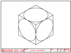 ISO CUBE |
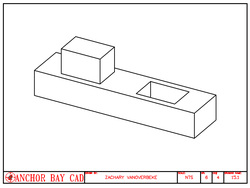
General
 GENERAL 15.13 |
Dimetric
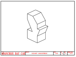 DIMETRIC 15.5 |
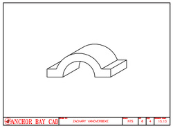
Cavalier
 CAVALIER 15.12 |
Trimetric
 TRIMETRIC 15.1 |
Cabinet
 CABINET 15.11 |
